|
|
感谢关注耳机俱乐部网站,注册后有更多权限。
您需要 登录 才可以下载或查看,没有账号?注册

x
本帖最后由 vcflash 于 2020-6-20 08:48 编辑
在网上找的一个关于ROSSINI+CLOCK的技术测试帖
原文地址:https://www.stereophile.com/content/dcs-rossini-player-rossini-clock-measurements
I measured the dCS Rossini with my newly recalibrated Audio Precision SYS2722 system (see the January 2008 "As We See It"). As well as test CDs and the Audio Precision's serial digital outputs, I used WAV and AIFF test-tone files sourced via USB from my MacBook Pro running on battery power and played with Pure Music 3.0. I began the testing with the first sample, but continued with the second sample. The Rossini Clock was used for all tests. Apple's USB Prober utility identified the Rossini as "dCS Rossini Player USB class 2" from "Data Conversion Systems Ltd," and revealed that its USB port operated in the optimal isochronous asynchronous mode. Apple's AudioMIDI utility revealed that it accepted 24-bit integer data via USB sampled at all rates from 44.1 to 384kHz. I tested the transport's error correction with the Pierre Verany Digital Test CD. The Rossini played without glitches until the dropouts in the pit spiral reached 1.25mm in length. With the minimum track pitch, it had problems when the dropouts reached 1mm in length, but this is still good performance, if not up to the standard set by the SACD transports in the Puccini and Vivaldi players. (The CD standard specifies only that a player cope with gaps up to 0.2mm long.) With up to six reconstruction filters available for PCM data, four low-pass filters for DSD data, and a choice of four maximum output levels, testing the Rossini was a complex and time-consuming task. The Rossini's maximum output level can be set to 200mV, 600mV, 2V, or 6V, which was confirmed by my measurements at both the balanced and unbalanced jacks. Unless stated otherwise, all subsequent testing was performed with the output set to 6V and the DSD filter set to F1 (footnote 1). Both sets of outputs preserved absolute polarity, the XLRs being wired with pin 2 hot. The balanced output impedance was extremely low, at 2 ohms, the unbalanced impedance higher, at 51 ohms—still low in absolute terms. The Rossini's impulse response with 44.1kHz data varied depending on which filter had been chosen. Filters 1–4 are all conventional FIR types, with the length of the filter decreasing from F1 to F4. Fig.1 shows the impulse response of F3. By contrast, F5's impulse response at reveals it to be a minimum-phase type (footnote 2), with all the ringing following the single sample at 0dBFS (fig.2); while F6 is again a linear-phase FIR type, similar to F1, with more coefficients than F2–F4. Tested with 44.1kHz-sampled white noise (footnote 3), F1 offers a very sharp rolloff above the audioband (fig.3, cyan and blue traces), with no trace of the aliased image at 25kHz of a full-scale 19.1kHz tone (magenta, red). Note also the very low level of harmonic-distortion components in this graph. The increasingly shorter impulse responses of filters F2–F4 result in increasingly slow rolloffs above the audioband, with reduced suppression of the 25kHz image. Fig.4, for example, was taken with F3; you can see that the image is just 23dB below the level of the 19.1kHz tone that produced it. F5 and F6 performed identically on this test; you can see from the spectral analysis with F5 (fig.5) that these filters are apodizing types, with a null at half the sample rate (indicated by the vertical green line). image: 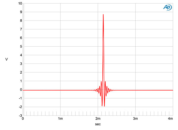
Fig.1 dCS Rossini, F3 filter, impulse response (one sample at 0dBFS, 44.1kHz sampling, 4ms time window).
image: 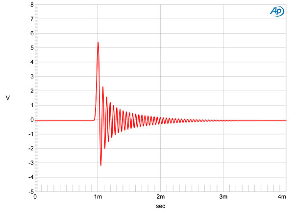
Fig.2 dCS Rossini, F5 filter, impulse response (one sample at 0dBFS, 44.1kHz sampling, 4ms time window).
image: 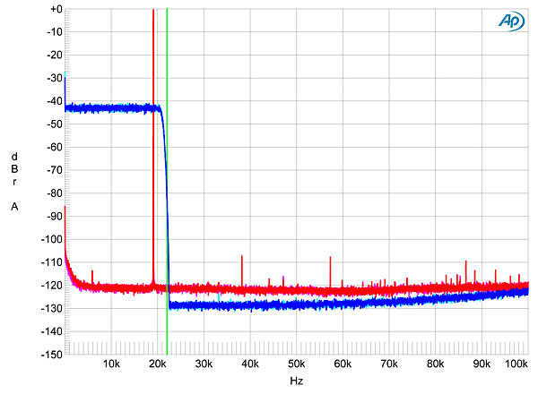
Fig.3 dCS Rossini, F1 filter, wideband spectrum of white noise at –4dBFS (left channel red, right magenta) and 19.1kHz tone at 0dBFS (left blue, right cyan), with data sampled at 44.1kHz (20dB/vertical div.).
image: 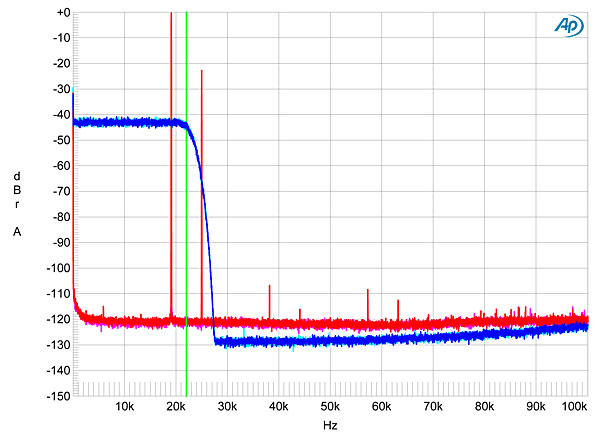
Fig.4 dCS Rossini, F3 filter, wideband spectrum of white noise at –4dBFS (left channel red, right magenta) and 19.1kHz tone at 0dBFS (left blue, right cyan), with data sampled at 44.1kHz (20dB/vertical div.).
image: 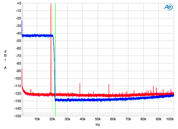
Fig.5 dCS Rossini, F5 filter, wideband spectrum of white noise at –4dBFS (left channel red, right magenta) and 19.1kHz tone at 0dBFS (left blue, right cyan), with data sampled at 44.1kHz (20dB/vertical div.).
Fig.6 is a more conventional graph of frequency response, taken with F1, and reveals a steep rolloff below half of each sample rate. F2–F4 had slower rolloffs above 20kHz, but none of them suffered any loss below 20kHz. Channel separation was superb, at >115dB below 10kHz, and the Rossini had a very low level of self noise, correlating with the superb resolution seen in fig.7. This graphs the spectra of the Rossini's output as it reproduced a dithered 1kHz tone at –90dBFS with first 16-bit, then 24-bit data. The increase in bit depth drops the noise floor by 21dB, suggesting resolution close to 20 bits' worth. Although some power-supply–related spuriae are apparent below 3kHz in this graph, these all lie below –134dB (0.00002%) and are therefore irrelevant. With its low noise and high resolution, the Rossini reproduced an undithered 16-bit tone at exactly –90.31dBFS with a superbly symmetrical waveform and the three DC voltage levels well defined (fig.8). With undithered 24-bit data at this low level, the dCS output a well-formed sinewave (fig.9). image: 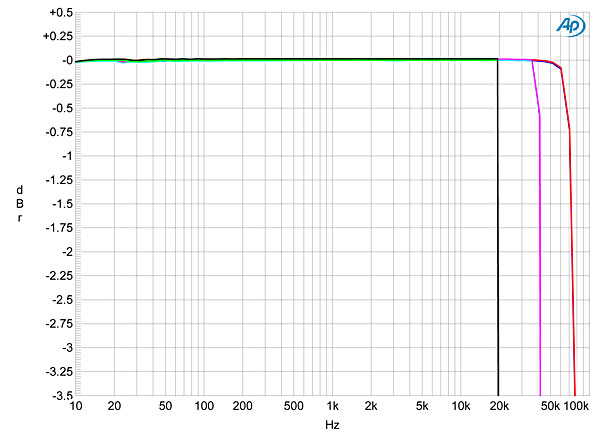
Fig.6 dCS Rossini, F1 filter, frequency response at –12dBFS into 100k ohms with data sampled at: 44.1kHz (left channel green, right gray), 96kHz (left cyan, right magenta), 192kHz (left blue, right red) (0.5dB/vertical div.).
image: 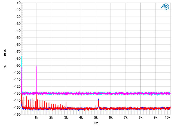
Fig.7 dCS Rossini, spectrum with noise and spuriae of dithered 1kHz tone at –90dBFS with: 16-bit data (left channel cyan, right magenta), 24-bit data (left blue, right red) (20dB/vertical div.).
image: 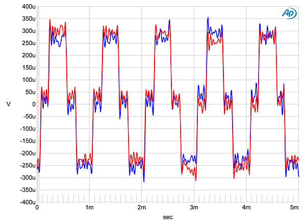
Fig.8 dCS Rossini, F1 filter, waveform of undithered 1kHz sinewave at –90.31dBFS, 16-bit data (left channel blue, right red).
image: 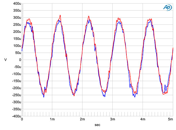
Fig.9 dCS Rossini, F1 filter, waveform of undithered 1kHz sinewave at –90.31dBFS, 24-bit data (left channel blue, right red).
The spectral analyses in figs. 3–5 suggest that the Rossini offered very little harmonic distortion, and this was confirmed by fig.10, taken with a full-scale 50Hz tone driven into a punishing 600 ohms. The highest-level harmonic is the third, but this still lies almost 130dB down! This graph was taken at 6V; at 2V maximum output level the third harmonic rose to –120dB, but this is still a vanishingly low level. image: 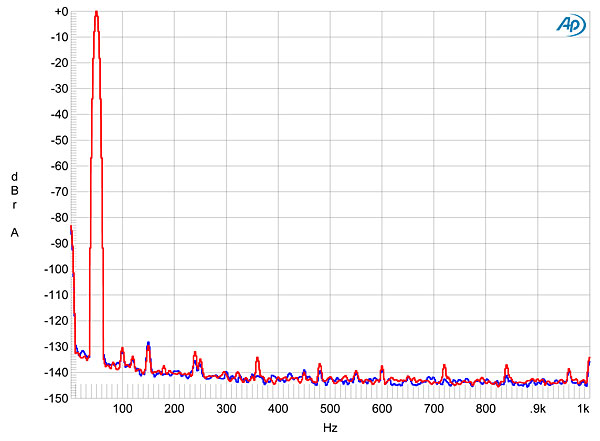
Fig.10 dCS Rossini, spectrum of 50Hz sinewave, DC–1kHz, at 6V into 600 ohms (left channel blue, right red; linear frequency scale).
I test for intermodulation distortion using an equal mix of 19 and 20kHz tones with the waveform peaking at 0dBFS; the resultant spectra of the Rossini's output varied with both the filter in use and the type of oversampling selected. Fig.11, for example, shows the result with F1 and upsampling to DXD (384kHz). Both intermodulation distortion and aliased images are MIA. When I switched to DSD upsampling (fig.12), some very low-level, higher-order intermodulation products can be seen, but the main difference is the rise in the ultrasonic noise floor. Switching to F2 with DSD (fig.13), the filter's slower rolloff allows images of the fundamental tones to appear. With F3 and F4, the even slower rolloff meant that I had to reduce the signal level by 3dB to get an audioband spectrum free from aliasing products (fig.14). On this test, F5 and F6 behaved identically to F1. image: 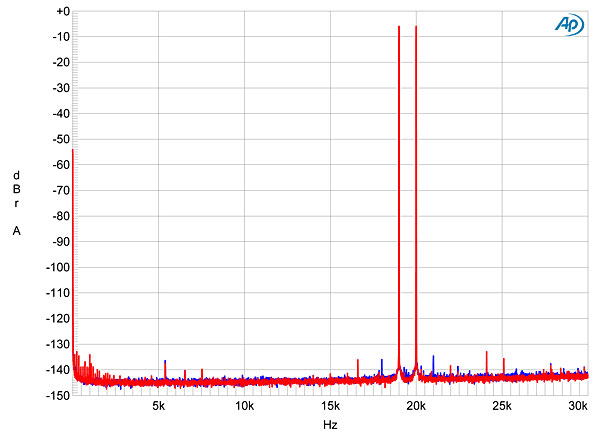
Fig.11 dCS Rossini, F1 filter, DXD upsampling, HF intermodulation spectrum, DC–30kHz, 19+20kHz at 0dBFS into 100k ohms, 44.1kHz data (left channel blue, right red; linear frequency scale).
image: 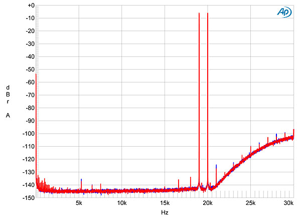
Fig.12 dCS Rossini, F1 filter, DSD upsampling, HF intermodulation spectrum, DC–30kHz, 19+20kHz at 0dBFS into 100k ohms, 44.1kHz data (left channel blue, right red; linear frequency scale).
image: 
Fig.13 dCS Rossini, F2 filter, DSD upsampling, HF intermodulation spectrum, DC–30kHz, 19+20kHz at 0dBFS into 100k ohms, 44.1kHz data (left channel blue, right red; linear frequency scale).
image: 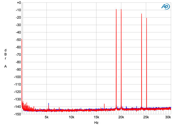
Fig.14 dCS Rossini, F4 filter, DXD upsampling, HF intermodulation spectrum, DC–30kHz, 19+20kHz at –3dBFS into 100k ohms, 44.1kHz data (left channel blue, right red; linear frequency scale).
Finally, the Rossini offered superb rejection of word-clock jitter in both its playback of CDs and through its serial data inputs. Fig.15, for example, shows the result of playing 16-bit J-Test data fed to the TosLink input. All the odd-order harmonics of the LSB-level squarewave are at the correct level (green line), and no jitter-related sidebands can be seen. With 24-bit J-Test data (fig.16), the spectrum is clean. image: 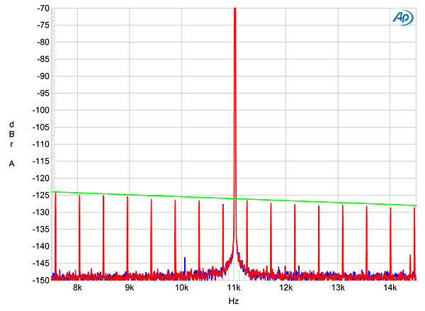
Fig.15 dCS Rossini, F1 filter, high-resolution jitter spectrum of analog output signal, 11.025kHz at –6dBFS, sampled at 44.1kHz with LSB toggled at 229Hz: 16-bit TosLink data (left channel blue, right red). Center frequency of trace, 11.025kHz; frequency range, ±3.5kHz.
image: 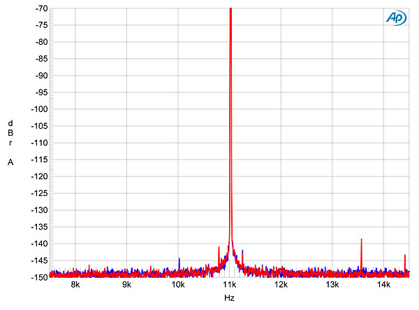
Fig.16 dCS Rossini, F1 filter, high-resolution jitter spectrum of analog output signal, 11.025kHz at –6dBFS, sampled at 44.1kHz with LSB toggled at 229Hz: 24-bit TosLink data (left channel blue, right red). Center frequency of trace, 11.025kHz; frequency range, ±3.5kHz.
The dCS Rossini offers measured performance that is about as good as can be gotten from a thoroughly modern digital audio product.—John Atkinson
Footnote 1: You can see the differing ultrasonic rolloffs of the Vivaldi's DSD filters in fig.10 here. F1 has the widest bandwidth. Footnote 2: This is at 44.1kHz. The F5 and F6 impulse responses vary with sample rate. Footnote 3: My thanks to Jürgen Reis of MBL for suggesting this test to me.
Read more at https://www.stereophile.com/cont ... IvegvhD3ZZ0R4qkc.99
|
|
 |联系我们|有害信息举报:010-60152166 邮箱:zx@jd-bbs.com|手机版|Archiver|黑名单|中国耳机爱好者俱乐部
( 京ICP备09075138号 )
|联系我们|有害信息举报:010-60152166 邮箱:zx@jd-bbs.com|手机版|Archiver|黑名单|中国耳机爱好者俱乐部
( 京ICP备09075138号 )


 发表于 2017-8-18 17:16:15
 提升卡
提升卡 变色卡
变色卡